The article presents a collection of electrical circuits of the car Nissan Almera 1995 to 2006.

The article presents a collection of electrical circuits of the car Nissan Almera 1995 to 2006.
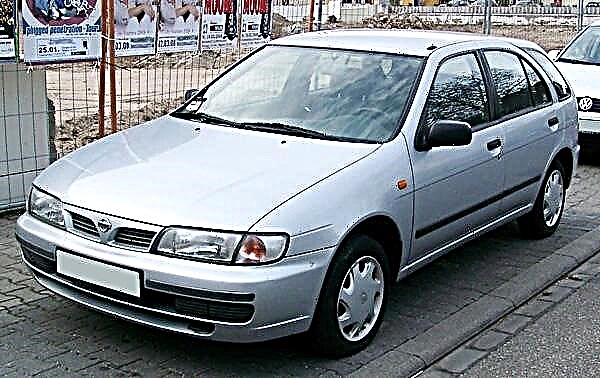
N16 (2000-2006). The cars of this generation were equipped with Nissan QG petrol engines with a volume of 1.5 and 1.8 liters, a 2.2-liter YD22DDT direct injection turbodiesel and a conventional YD22DDTi turbodiesel. Automatic transmissions were installed on models with an engine capacity of 1.8 liters. In the Japanese domestic market, the model was produced under the name Bluebird-Sylphy, in Singapore - under the name Nissan Sunny, where it was equipped with a 1.6 engine with automatic transmission.
By clicking on the photo, it will increase to your monitor screen size, then right-click and select "Save Image" in order to download the auto scheme to your computer.
Nissan Almera headlights switching circuit

I - high beam; II - low beam; III - high beam signaling; 1 - lighting switch; 2 - right headlight; 3 - left headlight; 4 - high beam thread; 5 - low beam thread; 6 - control lamp for turning on the high beam; 7 - pin connector of the main wiring harness.
Nissan Almera side light switching circuit

A - the first option; B - the second option; 1 - lighting switch; 2 - switch for rear fog lights; 3 - front left side light; 4 - front right side light; 5 - rear left side light; 6 - rear right side light; 7 - left lamp of license plate illumination; 8 - right license plate lamp.
Diagram: direction indicators and alarm

1 - alarm switch; 2 - direction indicator and alarm relay; 3 - turn signal switch; 4 - control lamp of the right direction indicator; 5 - control lamp of the left direction indicator; 6 - rear right direction indicator; 7 - right side direction indicator; 8 - front right direction indicator; 9 - rear left direction indicator; 10 - left side direction indicator.
Schematic: Nissan Almera Rear Fog Lights:

1 - lighting switch; 2 - relay for switching on the rear fog lamps; 3 - fog lamp switch; 4 - Nissan Almera fog lights.
Diagram of Nissan ECCS GA14DE and GA16DE engines:

1 - storage battery; 2 - ignition switch; 3 - power relay; 4 - fuel injectors; 5 - signal to the tachometer; 6 - control resistor; 7 - ignition distributor; 8 - switch (built into the ignition unit); 9 - capacitor; 10 - ignition coil; 11 - camshaft position sensor and engine crankshaft speed; 12 - spark plugs; 13 - meter for mass air flow; 14 - oxygen content sensor in exhaust gases; 15 - throttle position sensor; 16 - coolant temperature sensor; 17 - pressure sensor in the power steering system; 18 - KSUD controller; 19 - diagnostic connector; 20 - control lamp of malfunction of the KSUD; 21 - relay for turning on the fuel pump; 22 - fuel pump; 23 - tachometer; 24 - movement speed sensor; 25 - solenoid valve for exhaust gas recirculation and absorber blowdown; 26 - idle speed regulator; 27 - accelerated idle speed regulator; 28 - relay for switching on the electromagnetic clutch of the air conditioner compressor; 29 - relay for switching on the electric fans of the engine cooling system (on vehicles with a manual transmission); 30 - double relay for switching on / electric fans of the engine cooling system (on cars with an automatic transmission); 31 - single-speed electric fan of the engine cooling system; 32 - two-speed electric fan of the engine cooling system; 33 - compressor refrigerant pressure sensor; 34 - ECU of prohibition of engine start; 35 - position sensor of the gear shift lever; 36 - selector lever position sensor; 37 - ECU for air temperature in the passenger compartment with an evaporator sensor; 38 - heating and ventilation controls; 39 - controls for the climatic installation; 40 - to the time relay for turning on the rear window heating; 41 - to the air conditioner compressor; 42 - rear window heating switch; 43 - relay for turning on the rear window heating; 44 - outdoor lighting switch; 45 - "+" of the storage battery; 46 - "+" after the ignition switch or "+" when the starter is turned on.
Scheme of the KSUD Nissan ECCS engine SR20DE car Almera GTI:

1 - storage battery; 2 - ignition switch; 3 - controller enable relay; 4 - fuel injectors; 5 - signal to the tachometer; 6 - control resistor; 7 - ignition distributor; 8 - switch (built into the ignition distributor); 9 - capacitor (built into the ignition distributor); 10 - ignition coil; 11 - sensor of crankshaft position and engine crankshaft speed; 12 - spark plugs; 13 - meter for mass air flow; 14 - oxygen content sensor in exhaust gases; 15 - throttle position sensor; 16 - coolant temperature sensor; 17 - pressure sensor in the power steering system; 18 - KSUD controller; 19 - diagnostic connector; 20 - control lamp of malfunction of the KSUD; 21 - relay for turning on the fuel pump; 22 - fuel pump; 23 - tachometer; 24 - movement speed sensor; 25 - knock sensor; 26 - solenoid valve for recirculation of exhaust gases and blowdown of the absorber; 27 - idle speed regulator; 28 - accelerated idle speed regulator; 29 - double relay for turning on the electric fans of the engine cooling system (on vehicles with an automatic transmission); 30 - relay for switching on the electric fans of the engine cooling system (on vehicles with a manual transmission); 31 - two-speed electric fan of the engine cooling system; 32 - single-speed electric fan of the engine cooling system; 33 - intake air temperature sensor; 34 - air conditioner refrigerant pressure sensor; 35 - to the cabin air temperature control unit; 36 - ECU of prohibition of engine start; 37 - sensor of the position of the gear shift lever; 38 - selector lever position sensor; 39 - "+" after turning on the ignition or "+" when turning on the starter; 40 - "+" of the storage battery; 41 - relay for switching on the electromagnetic clutch of the air conditioner compressor; 42 - outdoor lighting switch; 43 - relay for turning on the rear window heater; 44 - rear window heater switch; 45 - to the air conditioner compressor; 46 - to the time relay for the rear window heater.
Schematic: CD20 engine management system

1 - storage battery; 2 - instrument and starter switch; 3 - sensor of the left key in the lock of the instrument and starter switch; 4 - relay for pre- and post-start heating; 5 - heating plugs; 6 - relay for turning on the electric fans of the engine cooling system at 1st speed; 7 - relay for switching on the electric fans of the engine cooling system at the 2nd speed; 8 - electric fans of the engine cooling system; 9 - electronic control unit (ECU); 10 - "+" after installing the key in the lock of the instrument and starter switch to position "3" or "+" of the starter; 11 - "+" of auxiliary equipment or "+" after turning on the instrument switch and starter; 12 - "+" from the storage battery; 13 - control lamp for preheating; 14 - speedometer; 15 - vehicle speed sensor; 16 - injection pump; 17 - solenoid valve for stopping the diesel engine; 18 - solenoid valve for adjusting the fuel injection advance angle; 19 - engine crankshaft speed sensor; 20 - coolant temperature sensor; 21 - refrigerant pressure sensor; 22 - accelerated idle solenoid valve; 23 - to the tachometer; 24 - control unit for regulating the temperature of the air in the passenger compartment; 25 - evaporator sensor; 26 - to the air conditioner compressor; 27 - controls for ventilation in the cabin; 28 - air conditioner controls; 29 - relay for switching on the electromagnetic clutch of the air conditioner compressor.
Fog lamp wiring diagram

1 - lighting switch; 2 - relay for turning on fog lights; 3 - fog lamp switch; 4 - left fog lamp; 5 - Nissan Almera right fog lamp.
Central locking of door locks

1 - thermal switch; 2 - electronic control unit for locking the door locks; 3 - switch for blocking the door lock from the driver's side; 4 - thermal switch for the electric motor of the door lock drive; 5 - electric motor of the drive of the front left door lock; 6 - electric motor of the drive of the front right door lock; 7 - electric motor of the drive of the rear left door lock; 8 - electric motor of the drive of the rear right door lock; 9 - door drive position sensor.
Auto reverse light circuit

A - with a hatchback body; B - with a sedan body; 1 - reversing light switch; 2 - selector on cars with an automatic transmission; З - left reversing lamp; 4 - right reversing light.
Air conditioning system diagram

A - gasoline engine; B - diesel engine; 1 - fan drive electric motor; 2 - resistance of the fan drive electric motor; 3 - air conditioner mode switch; 4 - air conditioner switch; 5 - control unit; 6 - electric motor of the air distribution flap drive; 7 - recirculation switch; 8 - relay for turning on the air conditioner; 9 - double pressure sensor; 10 - thermal switch of the air conditioner compressor; 11 - air conditioner compressor; 12 - solenoid valve for forced idle control; 13 - the first relay of the electric fan; 14 - the second relay of the electric fan; 15 - the third relay of the electric fan; 16 - electronic engine control unit; 17 - the first electric fan; 18 - the second electric fan.