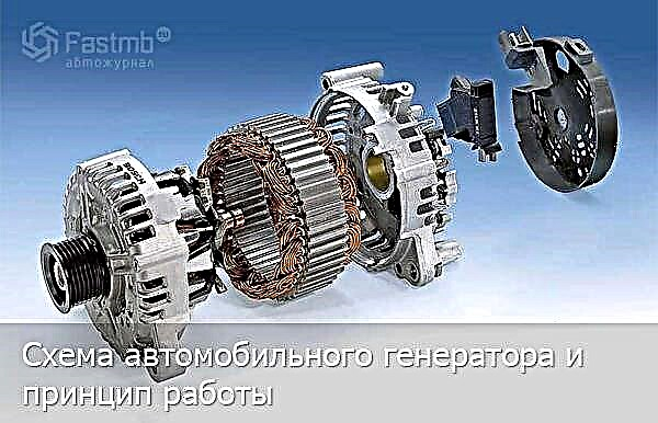
The article describes a detailed structure and diagram of an automobile generator, as well as its principle of operation. A diagram of the connections of the VAZ 2110 and 2106 generator system is given.

An electrical machine that converts mechanical energy into electrical current is called an automobile generator. The generator's function in a car is to charge the battery and power electrical equipment with the engine running. An alternator serves as a vehicle generator.
The generator is located in the engine, most often in its front part, driven from the crankshaft. On hybrid vehicles, the alternator does the work of a starter-alternator, and a similar arrangement is used in some other stop-start systems. Denso, Delphe and Bosch are currently the world's leading generators.
There are two types of automotive alternator designs: compact and traditional. The differences that characterize these types consist of the difference in the fan layout, differ in the housing design, rectifier unit and drive pulley, geometric dimensions. Common parameters found in both types of car generators are:
- Rotor;
- Stator;
- Frame;
- Voltage regulator;
- Rectifier unit;
- Brush assembly.
Diagram of a VAZ 2106 automobile generator:

| 1 - clamping sleeve | 14 - conclusion "67" |
| 2 - bushing | 15 - neutral wire plug |
| 3 - buffer sleeve | 16 - generator mounting stud |
| 4 - back cover | 17 - fan impeller |
| 5 - screw for fixing the rectifier unit | 18 - pulley |
| 6 - rectifier unit | 19 - plates |
| 7 - valve (diode) | 20 - ring |
| 8 - rear bearing | 21 - front bearing |
| 9 - slip rings | 22 - rotor winding |
| 10 - rotor shaft | 23 - rotor |
| 11 - brushes | 24 - stator winding |
| 12 - conclusion "30" | 25 - stator |
| 13 - brush holder | 26 - front cover |
Diagram of an automobile generator VAZ 2110:

| 1 - casing | 17 - pulley |
| 2 - output "B +" for connecting consumers | 18 - nut |
| 3 - interference suppression capacitor 2.2 μF | 19 - rotor shaft |
| 4 - common terminal of additional diodes (connected to the terminal "D +" of the voltage regulator) | 20 - front bearing of the rotor shaft |
| 5 - holder of positive diodes of the rectifier unit | 21 - beak-shaped pole pieces of the rotor |
| 6 - holder of negative diodes of the rectifier unit | 22 - rotor winding |
| 7 - conclusions of the stator winding | 23 - bushing |
| 8 - voltage regulator | 24 - clamping screw |
| 9 - brush holder | 25 - rear rotor bearing |
| 10 - back cover | 26 - bearing sleeve |
| 11 - front cover | 27 - slip rings |
| 12 - stator core | 28 - negative diode |
| 13 - stator winding | 29 - positive diode |
| 14 - distance ring | 30 - additional diode |
| 15 - washer | 31 - terminal "D" (common output of additional diodes) |
| 16 - conical washer |
Generator system wiring diagram:

1 - generator; 2 - negative diode; 3 - additional diode; 4 - positive diode; 5 - control lamp for battery discharge; 6 - instrument cluster; 7 - voltmeter; 8 - mounting block; 9 - additional resistors of 100 Ohm, 2 W; 10 - ignition relay; 11 - ignition switch; 12 - storage battery; 13 - capacitor; 14 - rotor winding; 15 - voltage regulator
The main task of the rotor - create a rotating magnetic field, for this purpose, the excitation winding is located on the rotor shaft. It fits in two pole halves, each pole half has six protrusions - they are called beaks. There are also slip rings on the shaft, there are two of them, and it is through them that the excitation winding is powered. Rings are most often made of copper; steel or brass rings are quite rare. The excitation winding leads are soldered directly to the rings. One or two fan impellers are placed on the rotor shaft (their number depends on the design) and the driven drive pulley is fixed. Two maintenance-free ball bearings form the rotor bearing assembly. On the side of the slip rings, a roller bearing can also be located on the shaft.
The stator is necessary to create an alternating electric current, combines a metal core and windings, the core is made up of plates, they are made of steel. It has 36 slots for winding windings, windings are laid in these slots, there are three of them, they form a three-phase connection. There are two ways of laying the windings in the grooves - the wave method and the looped one. The windings are connected to each other according to the "star" and "delta" schemes.
What are these schemes?
- "Star" - some ends of the windings are connected at one point, and the other ends are leads;
- "Triangle" - a circular connection of the ends of the windings in sequence, the conclusions come from the connection points.
Most of the structural elements of the generator are located in the housing. It consists of two covers - front and back. The front is located on the side of the drive pulley, the rear is located on the side of the slip rings. The covers are bolted together. The manufacture of lids is most often practiced from an aluminum alloy. It is non-magnetic, lightweight and capable of dissipating heat easily. There are ventilation windows on the surface of the covers, and two or one fixing paws. Depending on the number of legs, the generator mount is called one-leg or two-leg.
The brush assembly serves to ensure the transfer of the excitation current to the contact rings. It consists of two graphite brushes, springs that press them, and a brush holder. In generators of modern machines, the brush holder is located with a voltage regulator in a single non-separable unit.
The rectifier unit performs the function of converting the sinusoidal voltage, which is generated by the generator, into the DC voltage of the vehicle's on-board network. These are plates that act as heat sinks with mounted diodes. The block contains six power semiconductor diodes, for each phase there are two diodes, one for the "positive" and the other for the "negative" output of the generator.
On many generators, the field winding is connected through a separate group, which consists of two diodes. These rectifiers prevent the discharge of the battery discharge current through the winding when the engine is not running. When the windings are connected according to the "star" principle, two additional power diodes are installed at the zero terminal, allowing the generator power to be increased by up to 15 percent. The rectifier unit is switched off into the generator circuit at special mounting sites by soldering, welding, or bolting.
Voltage regulator - its purpose is to maintain the generator voltage within certain limits. Currently, generators are equipped with semiconductor electronic (or integral) voltage regulators.
Voltage regulator designs:
- hybrid design - the use of radio elements and electronic devices in an electronic circuit together;
- integral design - all components of the regulator (excluding the output stage) are made using thin-film microelectronic technology.
Voltage stabilization, which is necessary when changing the speed of the load and engine crankshaft, is carried out automatically by acting on the current in the field winding. The regulator controls the frequency of the current pulses and the duration of the pulses.
The voltage regulator changes the voltage supplied for charging the storage battery by temperature compensation of the voltage (depending on the air temperature). The higher the air temperature, the less voltage goes to the battery.
The generator is driven by a belt drive; it rotates the rotor at a speed that is two to three times higher than the crankshaft speed. In different designs of the generator, a poly V-belt or a V-belt can be used:
- V-belt has the prerequisites for rapid wear (this depends on the specific pulley diameter), since the field of application of the V-belt is limited by the dimensions of the driven pulley.
- V-ribbed belt it is considered more universal, applicable for small diameters of the driven pulley, with its help a larger gear ratio is realized. Modern generator models have a poly V-belt in their designs.
There is a generator called inductor, that is, brushless. It has a rotor consisting of a set of compressed thin plates made of transformer iron, the so-called soft magnetic passive ferromass rotor. The excitation rewind is placed on the stator. By changing the magnetic conductivity of the air gap between the stator and the rotor, an electromotive force is obtained in such a generator.
How a car generator works

When the key is turned in the ignition lock, current flows to the field winding through the brush assembly and slip rings. A magnetic field is induced in the winding. The rotor of the generator begins to move with the rotation of the crankshaft. The stator windings are penetrated by the rotor's magnetic field. An alternating voltage occurs at the terminals of the stator windings. When a certain speed is reached, the excitation winding is powered directly from the generator, that is, the generator goes into self-excitation mode.
The AC voltage is converted into DC by the rectifier unit. In this state, the generator is engaged in providing the required current to charge the power supply to consumers and the battery.
The voltage regulator turns on when the load and the crankshaft speed change. He is engaged in adjusting the turn-on time of the excitation winding. The time to turn on the field winding decreases with a decrease in the external load and an increase in the generator rotation frequency. The time increases with increasing load and decreasing speed. When the consumed current exceeds the capabilities of the generator, the storage battery is switched on. There is a warning lamp on the dashboard that monitors the operating condition of the generator.
The main parameters of the generator:
- Rated voltage;
- rated excitation frequency;
- rated current;
- self-excitation frequency;
- Efficiency (coefficient of performance).
The nominal voltage is 12 or 24 V, the voltage value depends on the design of the electrical system. The rated current is the maximum recoil current at the rated speed (it is 6,000 rpm).
Current-speed characteristic Is the dependence of the current strength on the generator rotation frequency.
In addition to the nominal values, the current-speed characteristic has other points:
- minimum current and minimum operating speed (40-50% of the rated current is the minimum current);
- maximum current and maximum speed (no more than 10% of the maximum current exceeds the nominal).